Flexure Based Dial Indicator (2022)

Screw stage

Intermediate Stage
Motivation:
This was a final project for my compliant machines class. This was a group project completed with two other students. I did some of the analysis as well as a large amount of CAD, manufacturing, ordering, and project management.
Description:
The project uses FDM Prusa 3D printed parts (which allowed for fast design iteration and varying thicknesses of the flexures) as well as plastic glue and M1 screws. The M1 screws are used for alignment, but the parts are ultimately attached with the glue (shear strength roughly double that of the PLA). Many of the parts used different print settings to allow them to come out.
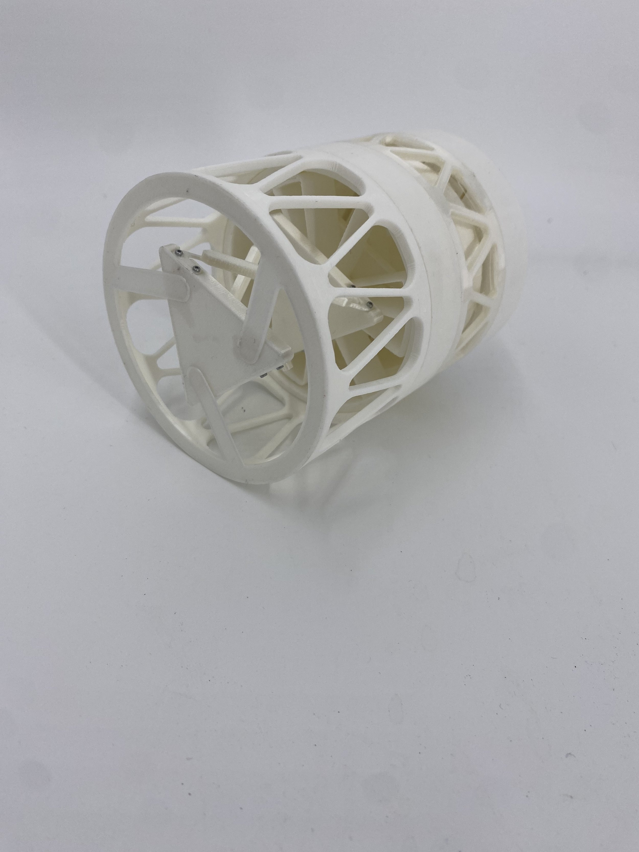
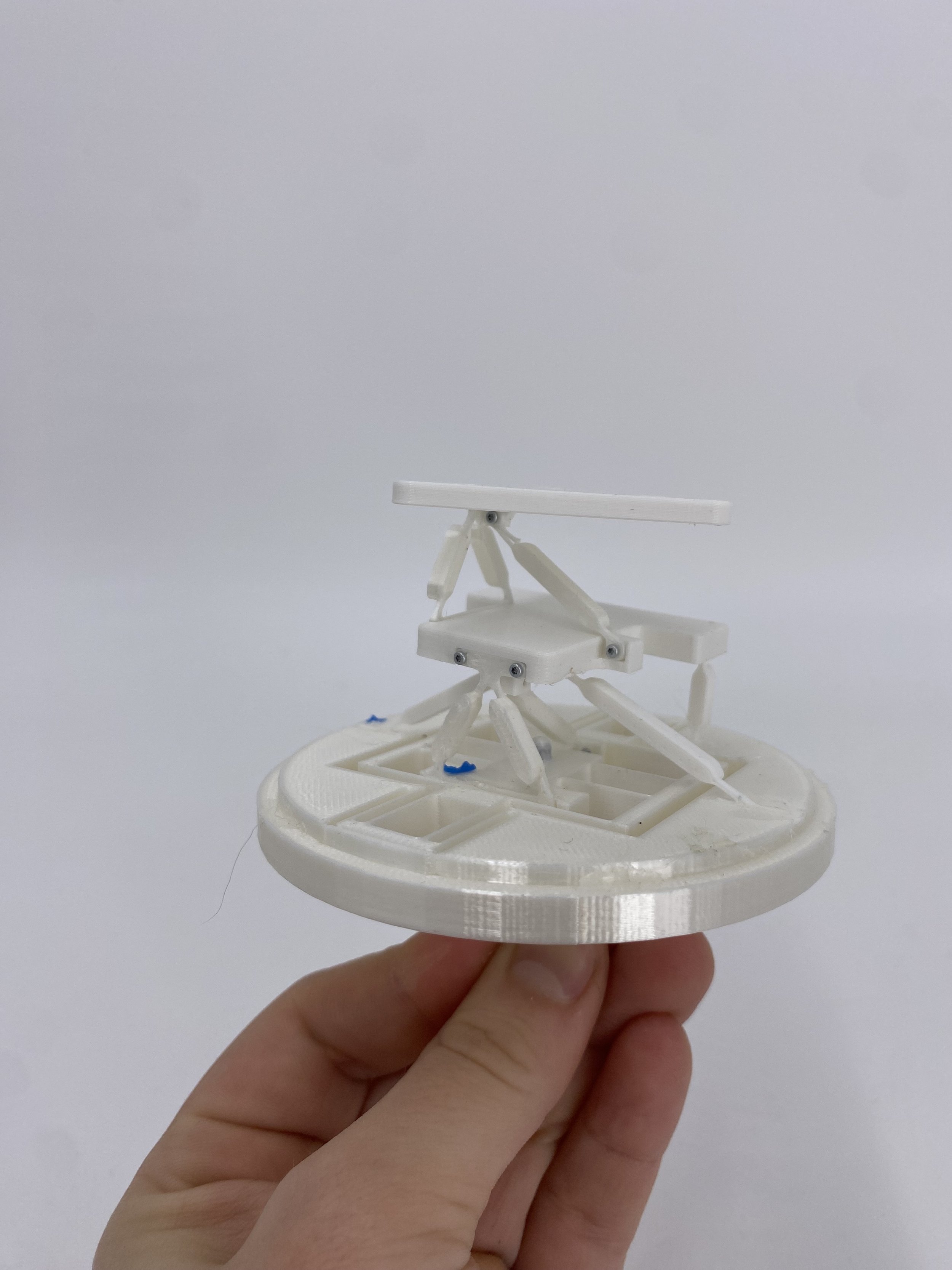
The dial indicator uses flexures for both constraint and motion. An xy stage takes the input at the bottom and then uses an intermediate stage to translate the motion into rotation. This rotation then uses a screw stage to take the rotational motion and create an output at the top.
Lessons Learned:
The force output at the top matters. We had originally planned to have an amplification stage, but realized that this created such a small force output at the top that we couldn’t measure the device. I learned a lot about how to tweak 3d printer settings. The rotational constraint flexures were the width of the 3d printer nozzle, which required a large amount of fidgeting with the settings. We used the FACT chart a great deal to create flexure designs as well as comparisons of stiffnesses in the stages.
Old version of intermediate stage which uses flexures as both constraints and actuators

xy stage